Seite 1 von 1
HM-LC-SWX-SM invertieren
Verfasst: 17.04.2019, 10:54
von maxx3105
Hallo könnte mir jemand einen Tipp geben wenn ich den Sketch invertieren möchte muss ich dann:
Code: Alles auswählen
// if A0 and A1 connected
// we use LOW for ON and HIGH for OFF
bool checkLowActive () {
  pinMode(14,OUTPUT); // A0
  pinMode(15,INPUT_PULLUP);  // A1
  digitalWrite(15,HIGH);
  digitalWrite(14,LOW);
  bool result = digitalRead(15) == LOW;
  digitalWrite(14,HIGH);
  return result;
hier ändern oder:
Code: Alles auswählen
#define CFG_LOWACTIVE_BYTE 0x00
#define CFG_LOWACTIVE_ON   0x01
#define CFG_LOWACTIVE_OFF  0x00

#define DEVICE_CONFIG CFG_LOWACTIVE_OFF
hier?
Re: HM-LC-SWX-SM invertieren
Verfasst: 17.04.2019, 11:02
von papa
Die Mechanismen sind beide da, um eine Firmware für unterschiedliche Anwendungen verwenden zu können. Mittels des ersten kann durch das Kruzschließen von 2 IO-Ports auf "low" Umgeschalten werden. Der andere Mechanismus nutzt den "eventuell verwendeten" OTA-Bootloader, um diese Information bereit zu stellen.
Um das Standardverhalten des Sketches umzustellen, muss einfach nur der Default umkonfiguriert werden:
Re: HM-LC-SWX-SM invertieren
Verfasst: 17.04.2019, 11:16
von maxx3105
Alles klar vielen Dank.
Re: HM-LC-SWX-SM invertieren
Verfasst: 20.04.2019, 12:11
von maxx3105
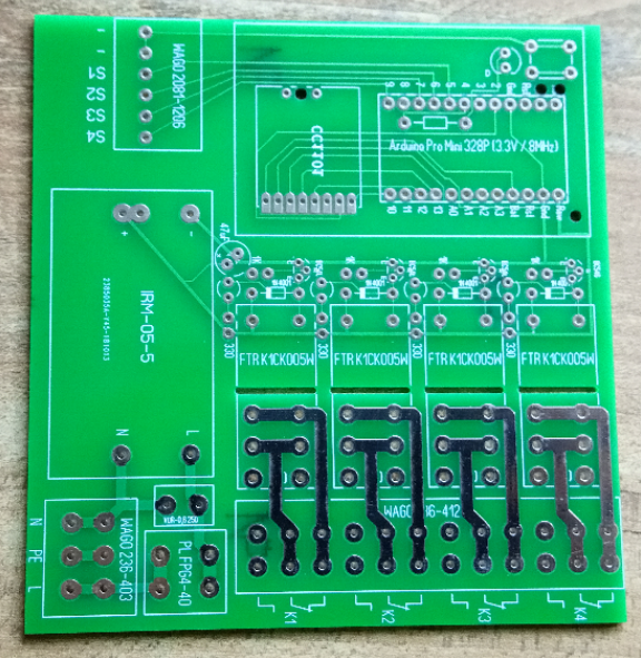
Ich habe nun das Problem das ich nur 1 Relaise über die PINs schalten kann. Ich verwende die Platine von Ronny Thomas HB-UNI-SenACT-4-4-PCB dort werden für das externe Schalten der Relaise PIN 5, 6, 7, und 9 verwendet.
Code: Alles auswählen
//- -----------------------------------------------------------------------------------------------------------------------
// AskSin++
// 2016-10-31 papa Creative Commons - http://creativecommons.org/licenses/by-nc-sa/3.0/de/
//- -----------------------------------------------------------------------------------------------------------------------

// define this to read the device id, serial and device type from bootloader section
// #define USE_OTA_BOOTLOADER

// number of relays by defining the device
#define HM_LC_SW1_SM 0x00,0x02
#define HM_LC_SW2_SM 0x00,0x0a
#define HM_LC_SW4_SM 0x00,0x03

#define CFG_LOWACTIVE_BYTE 0x00
#define CFG_LOWACTIVE_ON   0x01
#define CFG_LOWACTIVE_OFF  0x00

#define DEVICE_CONFIG CFG_LOWACTIVE_ON

#define HM_SENSOR_RELAY

#define EI_NOTEXTERNAL
#include <EnableInterrupt.h>
#include <AskSinPP.h>
#include <LowPower.h>

#include <Switch.h>


// we use a Pro Mini
// Arduino pin for the LED
// D4 == PIN 4 on Pro Mini
#define LED_PIN 4
// Arduino pin for the config button
// B0 == PIN 8 on Pro Mini
#define CONFIG_BUTTON_PIN 8

#ifdef HM_SENSOR_RELAY
  // relay pins for the HMSensor Relay Board
  #define RELAY1_PIN 17
  #define RELAY2_PIN 16
  #define RELAY3_PIN 15
  #define RELAY4_PIN 14
  #define BUTTON1_PIN 9
  #define BUTTON2_PIN 7
  #define BUTTON3_PIN 6
  #define BUTTON4_PIN 5
//#else
  // relay output pins compatible to the HM_Relay project
  //#define RELAY1_PIN 5
  //#define RELAY2_PIN 6
  //#define RELAY3_PIN 7
  //#define RELAY4_PIN 3
#endif

// number of available peers per channel
#define PEERS_PER_CHANNEL 8


// all library classes are placed in the namespace 'as'
using namespace as;

// define all device properties
const struct DeviceInfo PROGMEM devinfo = {
    {0x12,0x34,0x56},       // Device ID
    "papa000000",           // Device Serial
    {HM_LC_SW4_SM},         // Device Model
    0x16,                   // Firmware Version
    as::DeviceType::Switch, // Device Type
    {0x01,0x00}             // Info Bytes
};

/**
 * Configure the used hardware
 */
typedef AvrSPI<10,11,12,13> RadioSPI;
typedef AskSin<StatusLed<LED_PIN>,NoBattery,Radio<RadioSPI,2> > Hal;

// setup the device with channel type and number of channels
typedef MultiChannelDevice<Hal,SwitchChannel<Hal,PEERS_PER_CHANNEL,List0>,4> SwitchType;

Hal hal;
SwitchType sdev(devinfo,0x20);
#ifdef HM_SENSOR_RELAY
ConfigButton<SwitchType> cfgBtn(sdev);
InternalButton<SwitchType> btn1(sdev,1);
InternalButton<SwitchType> btn2(sdev,2);
InternalButton<SwitchType> btn3(sdev,3);
InternalButton<SwitchType> btn4(sdev,4);
#else
ConfigToggleButton<SwitchType> cfgBtn(sdev);
#endif

// if A0 and A1 connected
// we use LOW for ON and HIGH for OFF
bool checkLowActive () {
  pinMode(14,OUTPUT); // A0
  pinMode(15,INPUT_PULLUP);  // A1
  digitalWrite(15,HIGH);
  digitalWrite(14,LOW);
  bool result = digitalRead(15) == LOW;
  digitalWrite(14,HIGH);
  return result;
}

void initPeerings (bool first) {
  // create internal peerings - CCU2 needs this
  if( first == true ) {
    HMID devid;
    sdev.getDeviceID(devid);
    for( uint8_t i=1; i<=sdev.channels(); ++i ) {
      Peer ipeer(devid,i);
      sdev.channel(i).peer(ipeer);
    }
  }
}

void initModelType () {
  uint8_t model[2];
  sdev.getDeviceModel(model);
  if( model[1] == 0x02 ) {
    sdev.channels(1);
    DPRINTLN(F("HM-LC-SW1-SM"));
  }
  else if( model[1] == 0x0a ) {
    sdev.channels(2);
    DPRINTLN(F("HM-LC-SW2-SM"));
  }
  else {
    DPRINTLN(F("HM-LC-SW4-SM"));
  }
}


void setup () {
  DINIT(57600,ASKSIN_PLUS_PLUS_IDENTIFIER);
  bool first = sdev.init(hal);
#ifdef HM_SENSOR_RELAY
  bool low = false;
#else
  bool low = (sdev.getConfigByte(CFG_LOWACTIVE_BYTE) == CFG_LOWACTIVE_ON) || checkLowActive();
#endif
  DPRINT("Invert ");low ? DPRINTLN("active") : DPRINTLN("disabled");
  sdev.channel(1).init(RELAY1_PIN,low);
  sdev.channel(2).init(RELAY2_PIN,low);
  sdev.channel(3).init(RELAY3_PIN,low);
  sdev.channel(4).init(RELAY4_PIN,low);

  buttonISR(cfgBtn,CONFIG_BUTTON_PIN);
#ifdef HM_SENSOR_RELAY
  buttonISR(btn1,BUTTON1_PIN);
  buttonISR(btn2,BUTTON2_PIN);
  buttonISR(btn3,BUTTON3_PIN);
  buttonISR(btn4,BUTTON4_PIN);
#endif
  initModelType();
  initPeerings(first);
  sdev.initDone();
}

void loop() {
  bool worked = hal.runready();
  bool poll = sdev.pollRadio();
  if( worked == false && poll == false ) {
    hal.activity.savePower<Idle<> >(hal);
  }
}
Re: HM-LC-SWX-SM invertieren
Verfasst: 20.04.2019, 12:27
von jp112sdl
Frag mal Ronny... der hält ja seine Schaltungen unter Verschluss. Und die Community darf for free helfen...
Re: HM-LC-SWX-SM invertieren
Verfasst: 20.04.2019, 12:36
von maxx3105
Der HB-UNISen-Act-4-4 Sketch funktioniert ja einwandfrei nur der HM-LC-SWX-SM funktioniert über die Homematic auch nur von extern lässt sich nur das 4. Realaise schalten. In der standard Konfig des Sketches werden hiefür PIN 6, 3, 19 und 18 verwendet.